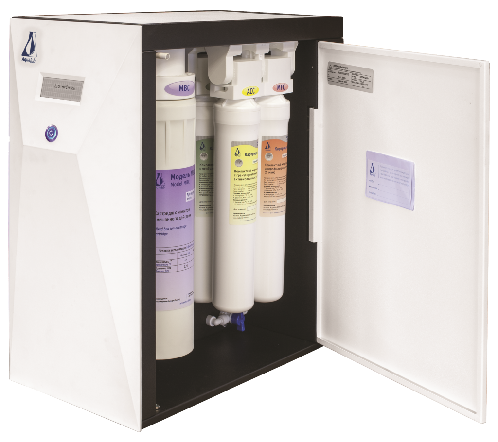
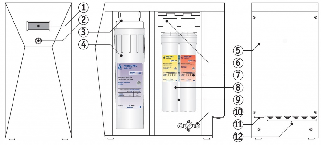
The Aqualab units Pure (P), Base (B), Base Double (D), Supreme (S) consist of a metal housing with cartridges, hydraulic and electrical systems inside. A plastic panel with a power button and a digital display is located on the front side of the housing. Hydraulic connection panel and a power cable connector are located on the back of the housing.
1 – Digital display
2 – Power button
3 – 15″ cartridge holders
4 – MBC 15″ cartridge
5 – Back cover
6 – 13″ cartridge holders
7 – MFC 13″ cartridge
8 – ACC 13″ cartridge
9 – ROC 13″ cartridge
10 – Ball valve B2
11 – Connector for power supply cable
12 – Hydraulic connection panel
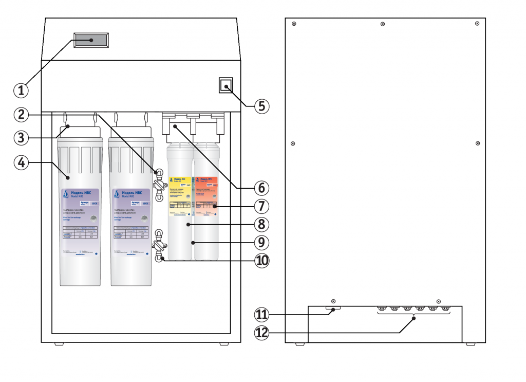
The Aqualab AL unit has a metal housing that holds inside cartridges, hydraulic and electrical systems. A panel with a power button and a digital display is located on the front side of the housing. A hydraulic connection panel and a power cable connector are located at the back of the housing. The cartridge compartment is accessed by opening the door with a concealed handle.
1 – Digital display
2 – Ball valve B3
3 – 15" cartridge holders
4 – MBC 15" cartridge
5 – Power switch
6 – 13" сartridge holders
7 – MFC 13" сartridge
8 – ACC 13" сartridge
9 – ROC 13" сartridge
10 – Ball valve B2
11 – Connector for power cable
12 – Panel with hydraulic connections
Main modules connection panel
Basic set of hydraulic connections for the main modules is described below. The number of connections may vary depending on the type of unit.
1 – Power cable connector
2 – HC4 "Filtrate".
Filtrate after all stages of purification
3 – HC5 "Concentrate".
Concentrate and cartridge rinse to drain.
4 – NS6 "Permeate".
Permeate from the membrane cartridges
5 – HC3 "Feed water".
Feed water connection
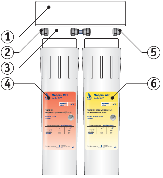
1 – Housing
2 – Water input connector
3 – 15" cartridge holder
4 – Cartridge#1
5 – Water output connector
6 – Cartridge # 2
Final purification units / Tap water desalination units
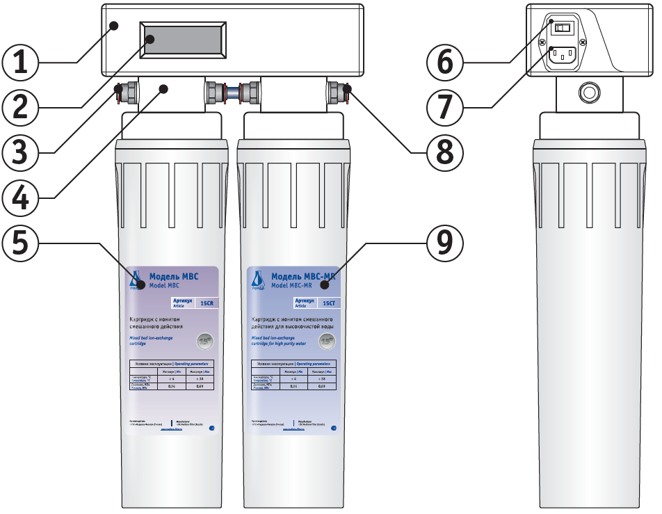
1 – Housing
2 – Digital display
3 – Water input connector
4 – 15" cartridge holder
5 – Cartridge #1
6 – Power switch
7 – Power cable connector
8 – Water output connector
9 – Cartridge #2
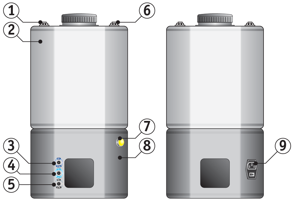
Storage and distribution systems
1 – ST5 "Return" connector
2 – Storage tank
3 – ST1 "Input" connector
4 – ST2 "Output" connector
5 – ST3 "Drain" connector
6 – ST4 "Breathing" connector
7 – Alarm lamp (low level in the tank)
8 – Stand
9 – Power cable connector and power switch
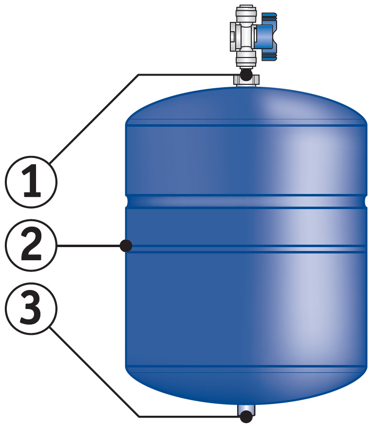
Pressurized storage systems
1 – Hydraulic connection with ball valve
2 – Pressure tank
3 – Air nipple
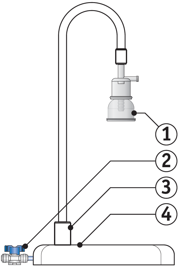
Manual dispensing systems
1 – Compact sterilizing microfilter
2 – Ball valve
3 – Tripod
4 – Base